DsPdf provides Surface, Layer, View, Space, and Visual classes in GrapeCity.Documents.Layout.Composition namespace that acts as a medium between the layout engine and the drawing surface, allowing you to draw complex graphics, text, and images. Furthermore, these classes also enable you to customize the z-order and clipping of the drawn graphics.
Surface is the main class in the Composition engine. Surface class contains a LayoutHost (the layout engine's root object) and one or more views (layers). Layers consist of visuals (drawable elements) and nested layers. The Render method of Surface class calls PerformLayout method of LayoutHost class to calculate the surface layout and then it draws all the layers, including nested ones, from the bottom to the top layer on the specified GcGraphics object
Layers are of two types: Layer and View class objects (derived from Layer objects). The View object encapsulates the LayoutView object, which represents a separate coordinate system with its own transformation matrix. The Layer object functions as a lightweight View with its own list of visuals, nested layers, and possible clipping area. The Surface object can only create Views, not Layers. However, each View object (as well as the Layer object) can create both nested Layers and nested Views. You must create at least one View on the Surface then use that View to create nested Layers (with the same transformation) or nested Views (with different transformation matrices).
Layers contain Visuals and Spaces. The Space object represents a LayoutRect that may affect the layout of other elements but is never drawn itself. Spaces are not part of the z-hierarchy of visual elements. The Visual class derives from the Space class. Visual class represents an element that will be drawn on the target GcGraphics. The Render method of the Surface class calls the special Draw delegate of the Visual and Layer classes (with the Visible property set to True) and passes the GcGraphics object and the current item (Layer or Visual) as parameters to the Draw delegate.
Refer to the following example code to draw a complex graphic with some text:
| C# |
Copy Code
|
|---|---|
// Initialize GcPdfDocument. var doc = new GcPdfDocument(); // Add a page to the PDF document. float pageW = 400; float pageH = 300; var page = doc.Pages.Add(new SizeF(pageW, pageH)); // Set text format. var fmt = new TextFormat { FontName = "Segoe UI", FontSize = 12f, ForeColor = Color.White }; // Initialize Surface. var sf = new Surface(); // Create LayoutView. var view = sf.CreateView(300, 200); // Create first figure. var fig1 = view.CreateVisual(); fig1.LayoutRect.AnchorTopLeft(null, 10, 10, 300, 200); fig1.Draw = (g, v) => { g.FillEllipse(v.AsRectF(), Color.LightSalmon); g.DrawString("1", fmt, new PointF(50, 50)); }; // Create second figure. var fig2 = view.CreateVisual((g, v) => { g.FillRoundRect(v.AsRectF(), 20, Color.MediumAquamarine); g.DrawString("2", fmt, new PointF(v.Width - 35, v.Height - 45)); }); fig2.LayoutRect.AnchorTopLeft(null, 50, 50, 300, 200); // Create third figure. view.CreateVisual((g, v) => { g.FillRectangle(v.AsRectF(), Color.CornflowerBlue); g.DrawString("3", fmt, new PointF(v.Width - 27, v.Height - 35)); }).LayoutRect.AnchorTopLeft(null, 90, 90, 300, 200); // Bring the first and second figures to the front. fig2.BringToFront(); fig1.BringToFront(); // Initialize GcPdfGraphics. var g = page.Graphics; // Render the surface. sf.Render(g); // Save the PDF document. doc.Save("Composition.pdf"); |
|

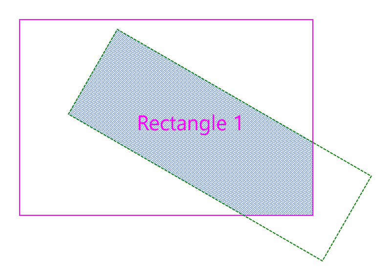
Any clipping specified on a Layer object applies to the layer's visuals and the nested layers. The Layer class provides two properties that allow you to define clipping: ClipRect and CreateClipRegion. You can specify just one of these two properties or both. The behavior is different in the three cases:
| C# |
Copy Code
|
|---|---|
// Initialize GcPdfDocument. var doc = new GcPdfDocument(); // Add a page to the PDF document. float pageW = 400; float pageH = 300; var page = doc.Pages.Add(new SizeF(pageW, pageH)); // Initialize Surface. var sf = new Surface(); // Create first LayoutView. var view = sf.CreateView(1, 1); // Create first sub-layer. var nestedLayer1 = view.CreateSubLayer(); // Create first figure. var rect = nestedLayer1.CreateVisual((g, v) => { g.DrawRectangle(v.AsRectF(), new Pen(Color.Magenta, 1)); g.DrawString("Rectangle 1", new TextFormat { FontName = "Segoe UI", FontSize = 16f, ForeColor = Color.Magenta }, new PointF(120, 90)); }); rect.LayoutRect.AnchorTopLeft(null, 20, 20, 300, 200); // Create second sub-layer. var nestedLayer2 = view.CreateSubLayer(); // Create second figure. nestedLayer2.CreateVisual((g, v) => { g.FillRectangle(v.AsRectF(), new HatchBrush(HatchStyle.Weave) { BackColor = Color.White, ForeColor = Color.RoyalBlue }); }).LayoutRect.AnchorExact(rect.LayoutRect); // Create second LayoutView. var view2 = sf.CreateView(1, 1).Translate(120, 30).Rotate(30); // Create clipping region. var clipRect = view2.CreateVisual((g, v) => { g.DrawRectangle(v.AsRectF(), Color.Green, 1, DashStyle.Dash); }).LayoutRect; clipRect.AnchorTopLeft(null, 0, 0, 300, 100); // Set clipping region. nestedLayer2.ClipRect = clipRect; // Bring first sub-layer to front. nestedLayer1.BringToFront(); // Initialize GcPdfGraphics. var g = page.Graphics; // Render the surface. sf.Render(g); // Save the PDF document. doc.Save("Clipping.pdf"); |
|
| C# |
Copy Code
|
|---|---|
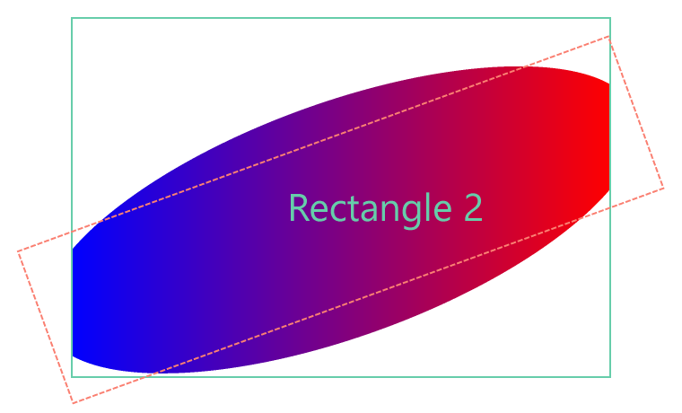
// Initialize GcPdfDocument. var doc = new GcPdfDocument(); // Add a page to the PDF document. float pageW = 600; float pageH = 600; var page = doc.Pages.Add(new SizeF(pageW, pageH)); // Initialize Surface. var sf = new Surface(); // Create first LayoutView. var view = sf.CreateView(1, 1); // Create first sub-layer. var nestedLayer1 = view.CreateSubLayer(); // Create first figure. var rect = nestedLayer1.CreateVisual((g, v) => { g.DrawRectangle(v.AsRectF(), new Pen(Color.MediumAquamarine, 1)); g.DrawString("Rectangle 2", new TextFormat { FontName = "Segoe UI", FontSize = 16f, ForeColor = Color.MediumAquamarine }, new PointF(120, 90)); }); rect.LayoutRect.AnchorTopLeft(null, 10, 40, 300, 200); // Create second sub-layer. var nestedLayer2 = view.CreateSubLayer(); // Create second figure. nestedLayer2.CreateVisual((g, v) => { var lgb = new LinearGradientBrush(Color.Blue, Color.Red); g.FillRectangle(v.AsRectF(), lgb); }).LayoutRect.AnchorExact(rect.LayoutRect); // Create second LayoutView. var view2 = sf.CreateView(1, 1).Translate(10, 140).Rotate(-20); var clipRect = view2.CreateVisual((g, v) => { g.DrawRectangle(v.AsRectF(), Color.Salmon, 1, DashStyle.Dash); }).LayoutRect; clipRect.AnchorTopLeft(null, 0, 0, 350, 90); // Create clipping region. nestedLayer2.ClipRect = clipRect; nestedLayer2.CreateClipRegion = (g, layer) => { var path = (GcBitmapGraphics.Path)g.CreatePath(); var rc = layer.ClipRect.AsRectF(); rc.Inflate(0, 20); path.PathBuilder.AddFigure(new EllipticFigure(rc)); return g.CreateClipRegion(path); }; nestedLayer2.SendToBack(); // Initialize GcBitmap. using var bmp = new GcBitmap(380 * 2, 230 * 2, true); using (var g = bmp.CreateGraphics(Color.White)) { g.Transform = Matrix3x2.CreateScale(2); // Render the surface. sf.Render(g); } // Initialize GcPdfGraphics. var gr = page.Graphics; // Draw the image. var image = bmp; gr.DrawImage(image, new RectangleF(30.6F, 30.7F, 40.8F, 100.9F), null, ImageAlign.Default); // Save the PDF document. doc.Save("ClippingEllipticalRegion.pdf"); |
|
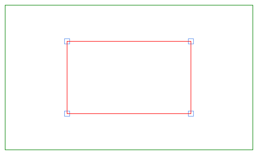
Layer class provides CreateVisual method that creates a Visual that is not associated with a LayoutRect. The position and size of the Visual are calculated based on one or several anchor points.
The anchor points assigned to AnchorPoints property of Visual class are recalculated to the View coordinate system and saved to Points property of Visual class before executing the Draw delegate of Visual class.
Refer to the following example code to draw a rectangle relative to anchor points:
| C# |
Copy Code
|
|---|---|
// Initialize GcPdfDocument. var doc = new GcPdfDocument(); // Add a page to the PDF document. float pageW = 400; float pageH = 300; var page = doc.Pages.Add(new SizeF(pageW, pageH)); // Initialize Surface. var sf = new Surface(); // Create LayoutView. var view = sf.CreateView(pageW, pageH); // Create margin rectangle. var marginRect = view.CreateVisual((g, v) => { g.DrawRectangle(v.AsRectF(), new Pen(Color.Green)); }).LayoutRect; marginRect.AnchorDeflate(null, 10); // Create points. var ap1 = marginRect.CreatePoint(0.25f, 0.25f); var ap2 = marginRect.CreatePoint(0.75f, 0.25f); var ap3 = marginRect.CreatePoint(0.75f, 0.75f); var ap4 = marginRect.CreatePoint(0.25f, 0.75f); var bluePen = new Pen(Color.CornflowerBlue); // Create anchor points. view.CreateVisual(new AnchorPoint[] { ap1 }, DrawAP); view.CreateVisual(new AnchorPoint[] { ap2 }, DrawAP); view.CreateVisual(new AnchorPoint[] { ap3 }, DrawAP); view.CreateVisual(new AnchorPoint[] { ap4 }, DrawAP); // Draw anchor points. void DrawAP(GcGraphics g, Visual v) { var pt = v.Points[0]; g.DrawRectangle(new RectangleF(pt.X - 5, pt.Y - 5, 10, 10), bluePen); } // Draw polygon through the anchor points. view.CreateVisual(new AnchorPoint[] { ap1, ap2, ap3, ap4 }, (g, v) => { g.DrawPolygon(v.Points, new Pen(Color.Red)); }); // Initialize GcPdfGraphics. var g = page.Graphics; // Render the surface. sf.Render(g); // Save the PDF document. doc.Save("AnchorPoints.pdf"); |
|
A Contour can be visualized similarly to anchor points. The Contour and AnchorPoints properties of Visual class are mutually exclusive; assigning both properties to non-empty values causes an exception when drawing the Surface. The Contour points are converted to regular points via Points property of Visual class before executing the Draw delegate. Then, you can use methods such as DrawPolygon of GcGraphics class to render the contour from the Draw delegate.
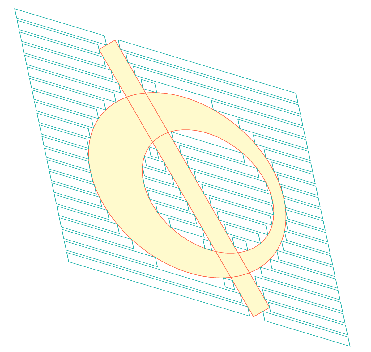
You may encounter a situation where there are several curves and you need to fill the space between them. The Draw delegate of Layer class enables you to fill the space between several contours. Each Contour can be associated with a separate Visual object on the same View or Layer. You can obtain an array of all visuals from the Draw delegate using GetVisuals method of Layer class. You can create a graphics path and add multiple contours as separate figures using the values of Points property of Visual class.
Refer to the following example code to draw multiple contours and fill the space between them by drawing multiple rectangles:
| C# |
Copy Code
|
|---|---|
    // Initialize GcPdfDocument.
    var doc = new GcPdfDocument();

    // Add a page to the PDF document.
    float pageW = 600;
    float pageH = 570;
    var page = doc.Pages.Add(new SizeF(pageW, pageH));

    // Initialize Surface.
    var sf = new Surface();

    // Create bar contour.
    var c1 = CreateBarContour(sf);

    // Create donut contour.
    var (c2, c3) = CreateDonutContours(sf);

    // Create first LayoutView.
    var view = sf.CreateView(1, 1, (g, l) =>
    {
        using var path = g.CreatePath();
        path.SetFillMode(FillMode.Winding);
        var figures = l.GetVisuals();
        for (int i = 0; i < figures.Length; i++)
        {
            var pts = figures[i].Points;
            path.BeginFigure(pts[0]);
            for (int j = 1; j < pts.Length; j++)
                path.AddLine(pts[j]);
            path.EndFigure(FigureEnd.Closed);
        }
        g.FillPath(path, Color.LemonChiffon);
        g.DrawPath(path, Color.Tomato, 1f);
    });

    // Create Visuals.
    view.CreateVisual(c1, false);
    view.CreateVisual(c2, false);
    view.CreateVisual(c3, false);

    // Create second LayoutView.
    var view2 = sf.CreateView(1, 1).Translate(-90, -20).Skew(30, 0).Rotate(20);

    // Draw rectangles.
    float top = 0f;
    var pen = new Pen(Color.LightSeaGreen);
    for (int i = 0; i < 22; i++)
    {
        DrawRects(view2, pen, top, c1, c2, c3);
        top += 20f;
    }

    // Initialize GcPdfGraphics.
    var g = page.Graphics;

    // Render the surface.
    sf.Render(g);

    // Save the PDF document.
    doc.Save("Contours.pdf");

    // Create bar contour.
    static Contour CreateBarContour(Surface surf)
    {
        // Create layout view for bar contour.
        var fig = surf.CreateView(1, 1).Translate(160, 80).Rotate(-30);

        // Create rectangular space.
        var sp = fig.CreateSpace().LayoutRect;
        sp.AnchorTopLeft(null, 0f, 0f, 30, 500);

        // Create contour.
        var c = fig.LayoutView.CreateContour();

        // Create points to anchor.
        c.AddPoints(new AnchorPoint[]
        {
sp.CreatePoint(0, 0),
sp.CreatePoint(1, 0),
sp.CreatePoint(1, 1),
sp.CreatePoint(0, 1)
        });
        return c;
    }

    // Create donut contour.
    static (Contour, Contour) CreateDonutContours(Surface surf)
    {
        // Create layout view for donut contour.
        var fig = surf.CreateView(1, 1).Translate(30, 100).Skew(20, 0);

        // Set dimensions of the donut contour.
        float rMax = 150;
        float xOffsetMax = 200;
        float yOffsetMax = 200;
        float rMin = 100;
        float xOffsetMin = 230;
        float yOffsetMin = 210;
        int nMax = 100;
        int nMin = 70;

        var maxPoints = new List<AnchorPoint>(nMax);
        var minPoints = new List<AnchorPoint>(nMin);
        double deltaMax = Math.PI * 2 / nMax;
        double deltaMin = Math.PI * (-2) / nMin;
        var lv = fig.LayoutView;

        for (int i = 0; i < nMax; i++)
        {
            double alpha = deltaMax * i;
            float x = (float)(Math.Cos(alpha) * rMax + xOffsetMax);
            float y = (float)(Math.Sin(alpha) * rMax + yOffsetMax);
            maxPoints.Add(lv.CreatePoint(0f, 0f, x, y));
        }
        for (int i = 0; i < nMin; i++)
        {
            double alpha = deltaMin * i;
            float x = (float)(Math.Cos(alpha) * rMin + xOffsetMin);
            float y = (float)(Math.Sin(alpha) * rMin + yOffsetMin);
            minPoints.Add(lv.CreatePoint(0f, 0f, x, y));
        }

        // Create contours.
        var c1 = lv.CreateContour();
        c1.AddPoints(maxPoints);

        var c2 = lv.CreateContour();
        c2.AddPoints(minPoints);

        return (c1, c2);
    }

    // Draw rectangles.
    static void DrawRects(View view, Pen pen, float top, params Contour[] contours)
    {
        LayoutRect? rPrev = null;
        while (true)
        {
            var r0 = view.CreateVisual((g, v) => {
                g.DrawRectangle(v.AsRectF(), pen);
            }).LayoutRect;
            if (rPrev is null)
                r0.AnchorTopLeft(null, top, 100);
            else
            {
                r0.SetTop(null, AnchorParam.Top, top);
                r0.SetLeft(rPrev, AnchorParam.Right);
            }
            r0.SetHeight(16);
            r0.AppendMaxRight(null, AnchorParam.Left, 500);

            var r1 = view.CreateSpace().LayoutRect;
            r1.SetTop(null, AnchorParam.Top, top);
            r1.SetHeight(16);
            r1.SetLeft(r0, AnchorParam.Right);
            r1.AppendMaxRight(null, AnchorParam.Left, 500);

            foreach (var c in contours)
            {
                r0.AppendMaxRight(c, ContourPosition.FirstInOutside);
                r1.AppendMaxRight(c, ContourPosition.NextOutOutside);
            }
            view.Surface.PerformLayout();
            if (r1.Width > 0f)
                rPrev = r1;
            else
            {
                ((Space)r1.Tag).Detach();
                break;
            }
        }
    }
|
|